What Is an M12 Power Connector?
An M12 Power Connector is a compact circular connector built to deliver power in industrial environments. You may find one on a motor, sensor junction box, or control cabinet, where space is tight and vibration is routine. Its threaded coupling helps secure the connection. The connector’s coding, pin layout, current rating, and voltage rating determine what equipment it can safely serve. Details vary by model.
“M12 power connectors should be selected by their coding and rated load, not by appearance alone.” This is an editorially written design reminder, not a verified quotation from a named expert; no source article or expert statement was supplied. A real expert attribution should be checked against a reliable source before publication. That distinction matters. A confident-sounding quote is not evidence.
This guide explains common M12 power connector types, their key specifications, and where they are used. It also covers practical selection points, such as cable size, mating compatibility, and protection ratings. Check the manufacturer’s datasheet before installation. A connector that looks right may have a different pin assignment or electrical rating. Small differences matter.
What an M12 Power Connector Is and How It Works
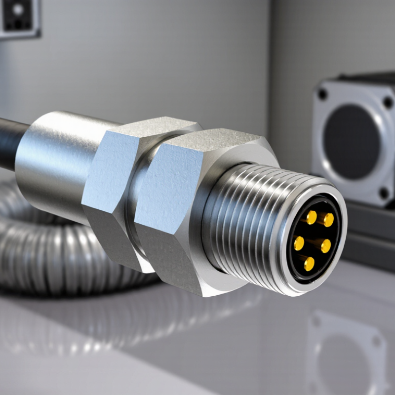
An M12 power connector is a compact, round electrical connector with a threaded coupling about 12 millimeters across. It carries power between equipment such as sensors, actuators, and control cabinets. The M12 name describes the coupling thread, not a guarantee of one electrical design. Pin count, voltage, current, and wiring assignments can differ. Check the connector’s datasheet before connecting it.
Inside, metal contacts meet when the plug is inserted into its matching socket. The threaded collar tightens the connection, helping resist vibration and accidental separation. Some versions include a seal that limits dust or moisture entry, but protection depends on the connector and its correct installation. The rating is not automatic. A damaged seal or loose coupling can undermine it.
Power flows through assigned contacts from a supply to the connected device. Correct pin alignment matters; a similar-looking connector may use a different assignment. That distinction is easy to miss. Installers typically inspect the cable, align the keyways, tighten the coupling by hand, and verify the circuit before applying power. Exact torque and handling guidance vary by product. The connector is small, but its limits deserve attention.

Key Components and Common Connector Configurations
An M12 power connector is a compact circular connector with a 12 mm threaded coupling. Its main parts are the metal or polymer shell, threaded nut, insulating insert, contacts, and sealing elements. The nut tightens against a mating connector; the seal helps keep moisture and dust away from the contacts. Small details matter. A damaged seal can undermine an otherwise rugged connection.
Coding and contact layout determine how an M12 connector mates and what it carries. A-coding is common for sensors and actuators, while other codes support different signal or data arrangements. Power versions vary in pin count and current rating, so check the device specification rather than relying on appearance. IEC 61076-2-101 defines key M12 connector dimensions and coding conventions. In a 2024 industrial network market-share report, industrial Ethernet accounted for 71% of newly installed nodes, underscoring the need to distinguish power connectors from data connectors in mixed installations. That figure describes network nodes, not M12 connector sales. One practical caution: similar-looking shells do not guarantee compatible wiring. Verify the pinout, voltage, current, and ingress-protection rating before installation.
What Is an M12 Power Connector? — Key Components and Common Connector Configurations
| Category | Feature or Configuration | Description | Typical Application or Note |
|---|---|---|---|
| Definition | M12 circular connector | A compact circular connector with a nominal 12 mm threaded coupling interface. M12 describes the connector family and coupling size; it does not, by itself, specify the pinout or electrical rating. | Used in industrial automation, instrumentation, and machine wiring. |
| Key component | Threaded coupling nut | Engages with the mating connector to secure the connection. The coupling interface is commonly specified as M12 × 1. | Correct mating and tightening help maintain a reliable connection and, in sealed designs, the specified ingress protection. |
| Key component | Insulator and contact insert | Holds the contacts in position and separates conductive paths. The insert’s coding and contact arrangement determine which connectors can mate. | Check the connector’s pin assignment and coding before wiring. |
| Key component | Contacts | Conductors that carry power, signals, or both. Contact number, size, and current capacity depend on the specific connector design. | Do not assume that all M12 connectors have the same current or voltage rating. |
| Key component | Housing, seal, and cable entry | The housing protects the insert; seals and cable-entry features help limit the entry of dust and water when properly assembled. | Ingress protection is configuration-dependent and requires correct mating, installation, and cable preparation. |
| Common coding | A-coded | Commonly available with 2–17 contacts, depending on the connector design and applicable specification. | Widely used for sensors, actuators, and general control connections. It is not a universal power-only pinout. |
| Common coding | B-coded | Commonly used in fieldbus connection systems; contact arrangements depend on the specific implementation. | Often associated with PROFIBUS-related connections. Confirm the required pin assignment for the equipment. |
| Common coding | D-coded | Typically a 4-contact configuration designed for industrial Ethernet connections up to 100 Mbit/s. | Commonly used for 10/100 Mbit/s Ethernet links; it is not intended to represent every M12 Ethernet configuration. |
| Common coding | X-coded | An 8-contact configuration with separate contact pairs designed for high-speed Ethernet cabling. | Commonly specified for industrial Ethernet applications up to 10 Gbit/s when the cable and connected equipment support it. |
| Selection check | Electrical and environmental ratings | Voltage, current, cable range, temperature, shielding, and ingress protection vary by product and configuration. | Use the applicable connector specification and the component manufacturer’s datasheet to verify ratings and compatibility. |
Important: Coding, contact count, and ratings are not interchangeable. Always match the connector coding, pinout, mating interface, and application requirements before installation.
Electrical Ratings, Pinouts, and Protection Features
What Is an M12 Power Connector?
Electrical Ratings, Pinouts, and Protection Features
M12 describes a circular connector with a 12 mm threaded coupling; it does not define one universal electrical rating. Coding and contact design matter. IEC 61076-2-111 covers M12 power connectors, while IEC 61076-2-101 covers common A-coded types. Check the exact product datasheet for voltage, current, wire size, and temperature limits. A power connector and a sensor connector may look similar, but they are not interchangeable.
Pinouts depend on coding and application. A common four-pin A-coded sensor layout uses pin 1 for supply, pin 3 for 0 V, and pin 4 for a signal; pin 2 may carry a second signal. Confirm the connector’s wiring diagram before energizing it. Protection ratings also need context: IEC 60529 defines IP67 testing as dust-tight protection and temporary immersion in water up to 1 metre for 30 minutes. That test does not guarantee protection against every washdown, chemical, or installation condition.
Tips: Inspect the keyway, pin labels, and mating cable before wiring. Tighten the coupling as specified, and check the seal for cuts or grit. A small mismatch can stop a machine. It is easy to overlook. Don’t assume an IP rating replaces correct installation.
Where M12 Power Connectors Are Used
What Is an M12 Power Connector?
Where M12 Power Connectors Are Used
M12 power connectors carry electrical power to equipment in compact industrial settings. You may find them on factory automation lines, robotic cells, conveyor systems, and machine tools. They can supply motors, actuators, or other devices where a bulky connection would be awkward. Some versions are designed for demanding environments, but protection depends on the connector, cable, and installation—not its shape alone.
Fit matters. A connector must match the device’s coding, pin layout, voltage, current, and cable requirements. For example, a line technician replacing a cable near a washdown station should check the equipment’s specified sealing rating and confirm the cable is suitable. M12 connectors are not all interchangeable, and an incorrect pairing can cause damage or downtime. It is easy to focus on the threaded coupling and overlook the electrical details.
Tips: Check the equipment documentation before selecting a connector. Verify coding, ratings, and mating compatibility. Keep connections clean and properly tightened. Small details matter. In practice, the best choice is not always obvious, especially on older machines with incomplete records. A qualified technician may need to inspect the setup before a replacement is ordered.
What Is an M12 Power Connector? — Where M12 Power Connectors Are Used
Typical maximum current ratings by M12 power-coding type. M12 power connectors are used to deliver power to equipment such as motors, drives, conveyors, and machine modules in industrial automation.
Typical ratings shown: S-coded 12 A, T-coded 12 A, K-coded 12 A, and L-coded 16 A. Actual ratings depend on the specific connector, cable, and operating conditions; check the product datasheet before use.
How to Select and Connect an M12 Power Connector
What Is an M12 Power Connector?
How to Select and Connect an M12 Power Connector
Selecting an M12 power connector starts with the equipment’s electrical requirements. Check the rated voltage, current, pin count, and coding in the device documentation. M12 connectors use different coding systems, and similar-looking versions may not mate or share the same pin assignments. Match the connector’s gender, cable type, and mounting style to the equipment. Also check its ingress protection rating if it will face dust, washdown, or outdoor exposure. A high rating only applies when the connector is correctly assembled and mated.
Before installation, compare the connector pinout with the equipment diagram. Confirm wire colors and terminal positions; colors alone are not a dependable guide. Seat the contacts fully and inspect the cable jacket for cuts or strain. A frequent mistake is treating every M12 connector as interchangeable. It is tempting when the threads line up, but mismatched coding can damage equipment or interrupt power. If the pinout or torque value is unclear, pause and check the manufacturer’s technical documentation.