2026 Top Expulsion Fuses for Global Buyers
For global buyers, choosing the right Expulsion Fuses is not a matter of comparing price tags alone. A pole-mounted cutout may look simple, yet its fuse link, voltage rating, and interrupting capability must suit the distribution network it protects. Thomas A. Short, an author on electric power distribution, offers a useful engineering reference. The line below is an editorial selection principle, not a verified verbatim quotation: “Choose protection for the network’s real conditions, not the catalog headline.”
Those conditions are tangible. Consider the system voltage, available fault current, expected load, and coordination with upstream devices. Then check the cutout’s construction, creepage distance, hardware, and compatibility with the specified fuse links. Heat, rain, salt spray, and altitude can also affect field performance. Small details matter.
This guide to 2026 options for global buyers focuses on those practical checks, alongside product documentation, supplier support, and clear technical specifications. A polished datasheet is useful, but it cannot replace careful review by a qualified power engineer. Nor does a popular product automatically fit every utility or installation. Buyers should compare verified ratings against their own project requirements and confirm unclear details with manufacturers. That extra step can feel slow. It may prevent an expensive mismatch later.
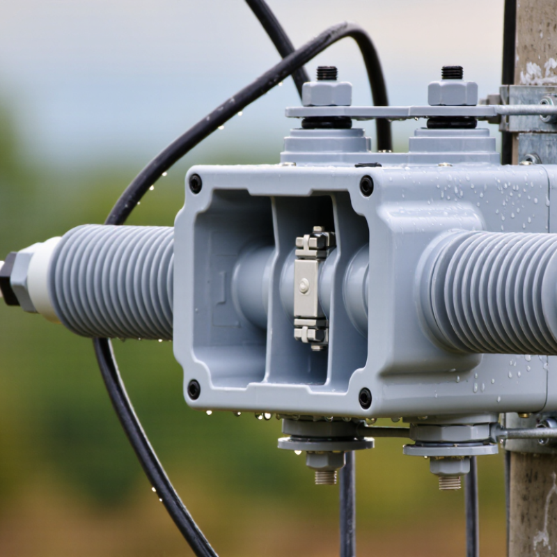
What Expulsion Fuses Are and How They Interrupt Fault Currents
An expulsion fuse is commonly used on overhead distribution lines to protect equipment from excessive current. Inside its tube, a fuse link melts when current rises beyond its rated limit. An arc forms across the break. The tube’s lining heats and releases gases, which help cool and deionize the arc. As alternating current reaches a natural zero crossing, the arc can be extinguished and the circuit interrupted. The fuse holder may then drop open, giving crews a visible indication of operation. Small details matter.
The interruption is not simply a wire snapping. Fuse ratings, available fault current, and the protected equipment’s characteristics must be considered together. If the fuse’s interrupting capacity is too low, it may not safely clear the fault. If its time-current response is poorly coordinated, an upstream device could operate unnecessarily, leaving a wider area without service. Engineers therefore check system voltage, load current, expected fault levels, and coordination with other protective devices. Field conditions matter, too: contamination, corrosion, and damaged contacts can affect performance.
After operation, the cause of the fault should be investigated before a replacement is installed. A fallen fuse can indicate a temporary event, but it can also point to damaged equipment or a persistent line fault. Replacement and inspection require appropriate procedures and qualified personnel; the open position alone does not prove nearby equipment is safe. Expulsion fuses are useful, but their limits deserve attention.
2026 Top Expulsion Fuses for Global Buyers - What Expulsion Fuses Are and How They Interrupt Fault Currents
| Topic | Factual overview | What global buyers should verify |
|---|---|---|
| What an expulsion fuse is | A high-voltage fuse that interrupts excessive current by melting a fuse element inside an arc-extinguishing tube. Many distribution designs use a hinged, drop-out assembly. | Confirm the device type and construction suit the intended overhead or other application; designs and ratings differ by product and market. |
| How fault interruption works | When current melts the fuse element, an arc forms. Heat from the arc causes gas-generating material in the tube to produce gases; the resulting gas flow helps lengthen, cool, and deionize the arc. In an AC system, interruption is completed when the arc is extinguished at a current zero and does not restrike. | Check the manufacturer’s tested interrupting performance for the system voltage and available fault current. Do not infer breaking capacity from appearance or fuse-link size. |
| Typical applications | Commonly used on overhead distribution circuits and to protect distribution transformers, capacitor banks, and other equipment where the fuse’s ratings and coordination are suitable. | Review the system one-line diagram, equipment protection requirements, fault study, and local utility practices before specifying a fuse. |
| Voltage and insulation ratings | Expulsion fuses are available in multiple voltage classes. The rated maximum voltage and insulation level are specific to the assembly and its applicable standard. | Match the rated maximum voltage to the system, and check insulation level, including basic insulation level (BIL) where applicable, against site requirements. |
| Continuous-current rating | The continuous-current rating indicates the current the fuse assembly is designed to carry under stated conditions. It is not the same as the fuse link’s melting current or interrupting rating. | Check the assembly and link ratings, ambient conditions, loading profile, and any required derating in the technical documentation. |
| Interrupting rating | This is the maximum fault current the fuse is designed and tested to interrupt at specified conditions. It must be adequate for the prospective fault current at the installation point. | Compare the published interrupting rating with the calculated available fault current at the relevant voltage; account for the applicable test basis. |
| Fuse-link characteristics | Fuse links have time-current characteristics that determine how quickly they respond to different overcurrents. Common link classes and designations vary by standard and application. | Select the link using load and inrush data, protected-equipment limits, and coordination with upstream and downstream protective devices. Confirm physical and electrical compatibility with the fuse holder. |
| Drop-out indication | In many cutout designs, operation releases the fuse carrier so it drops open, providing a visible indication that the fuse has operated. This indication does not by itself prove the circuit is safe to touch. | Follow approved isolation, testing, grounding, and safe-work procedures; never treat a visible open position as a substitute for verifying absence of voltage. |
| Load switching | A standard expulsion fuse is primarily an overcurrent protection device and is not automatically suitable for interrupting normal load current. Some systems use specifically rated load-break accessories or separate switching devices. | Verify the assembly’s explicit load-break rating and operating procedure. Use a suitable switch where the fuse arrangement is not rated to interrupt load current. |
| Environment and installation | Outdoor performance can depend on pollution, moisture, altitude, temperature, corrosion exposure, mounting orientation, and clearance. The applicable limits are product-specific. | Check the installation instructions, environmental limits, creepage and clearance requirements, mounting arrangement, and local electrical codes. |
| Standards and compliance | Applicable requirements depend on region and product category. Relevant frameworks may include IEC 60282-2 for expulsion fuses and applicable IEEE C37 fuse standards. | Specify the required standard and edition, request test documentation and certifications, and confirm acceptance with the authority having jurisdiction or utility. |
| Selection checklist | A sound selection considers system voltage, insulation level, continuous current, prospective fault current, time-current behavior, protected-equipment limits, coordination, and operating conditions. | Review the complete assembly and compatible fuse link as a matched protection solution; verify nameplate data and technical documentation before purchase and installation. |
Note: Ratings, link designations, test requirements, and permitted applications vary by product and jurisdiction. Use the applicable standard and manufacturer documentation for final selection.