What Is MIG Welding and How Does It Work?
Mig Welding, commonly called gas metal arc welding (GMAW), joins metal by creating an electric arc between a continuously fed wire electrode and the workpiece. The arc melts the wire and a small area of the base metal, forming a molten pool that cools into a joint. Shielding gas flows through the welding gun to help protect that pool from contamination in the air. The process looks straightforward from a distance. In practice, small changes matter.
A welder guides the gun along the joint while the machine feeds wire at a selected speed. Voltage, wire-feed speed, travel speed, gas choice, and material thickness all affect the bead. Too much travel speed can leave a narrow, uneven weld; too little can cause excess buildup or burn-through on thin sheet. These details are why a sound setup and practice coupons matter before welding a finished part. MIG equipment is often used on mild steel, stainless steel, and aluminum, but each material may require different wire, gas, settings, and technique. It is not one-size-fits-all.
This guide explains the main equipment, how the arc and shielding gas work, and what beginners should consider when choosing settings. It also covers common weld defects and basic safety, including suitable eye protection, gloves, and ventilation. A clean bead can be satisfying. Still, appearance alone does not prove a joint is strong; inspection and correct technique count, too.
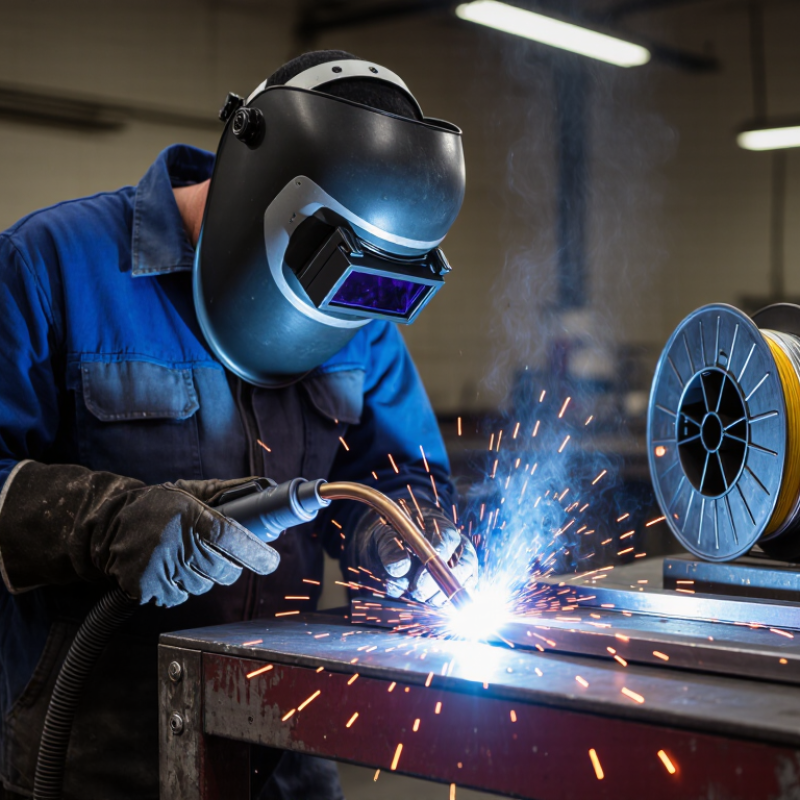
What MIG Welding Is
MIG welding, commonly called metal inert gas welding, joins metal using a continuously fed wire electrode. Technically, it is a form of gas metal arc welding (GMAW). An electric arc forms between the wire and the workpiece, creating a small molten pool. Shielding gas flows around the weld area, helping protect the molten metal from airborne contaminants. As the wire and base metal cool, they fuse into a joint. The wire also provides filler metal.
The process is valued for its steady wire feed and relatively quick operation, especially on clean steel and aluminum. The welder guides a torch along the seam while controlling wire speed, voltage, travel speed, and torch angle. Small changes matter. A slow pass can leave excess buildup, while moving too quickly may create a weak, uneven bead. MIG welding is not automatically easy or right for every joint. Surface condition, metal thickness, fit, and gas flow affect the result. Even experienced welders may need test pieces before making a critical weld.
Tips: Clean the metal first, check gas flow, and practice on scrap of similar thickness. Wear suitable eye and skin protection, and ensure good ventilation. Practice first. The bead may still look uneven; use that as a cue to review your settings and technique.

The Equipment and Materials Used in MIG Welding
MIG welding is commonly used for gas metal arc welding, or GMAW. Its core setup includes a constant-voltage power source, wire feeder, welding gun, work clamp, and shielding-gas system. The feeder pushes a continuous wire electrode through the gun, while the clamp completes the electrical circuit. A regulator and flowmeter control gas from the cylinder. Small parts matter. A blocked nozzle or loose connection can disturb the shielding and leave pores in the weld.
The wire must suit the base metal and joint: mild-steel wire, stainless wire, and aluminum wire are not interchangeable. The American Welding Society’s Welding Handbook, 9th edition, Volume 2, describes GMAW electrode diameters from about 0.6 to 1.6 millimeters. That range helps explain why wire size is chosen for the job, not by habit alone. Steel commonly uses argon-carbon dioxide shielding mixtures; aluminum generally uses argon or an argon-helium blend. Keep the gas choice matched to the wire and material. The awkward part is that charts cannot account for every draft, fit-up, or machine condition. Test beads on matching scrap can reveal problems before the final joint.
How the MIG Welding Process Works
MIG welding creates a joint by feeding a thin wire electrode through a welding gun. When the wire approaches the metal, an electric arc forms between them. The arc’s heat melts the wire and the edges of the workpiece, creating a small pool of molten metal. A shielding gas flows from the gun’s nozzle to help protect that pool from contamination in the air. The wire keeps advancing as the welder moves the gun along the joint.
Steady movement matters. Hold the gun at a consistent distance and angle, then travel at a pace that lets the weld pool form without spreading too far. Too much speed can leave a narrow, weak bead; too little may cause excessive buildup or burn-through on thin sheet metal. Small adjustments count. Wire-feed speed and voltage both affect how the arc sounds and how the bead settles. A crisp, even sound can be a useful clue, but it does not replace inspecting the finished weld.
Before striking an arc, clean away oil, paint, rust, and moisture near the joint. Clamp the work securely and attach the work lead to clean metal. Wear suitable eye and skin protection, and provide effective ventilation. A neat-looking bead can still hide poor fusion, so practice on scrap of similar thickness and inspect both sides when possible. That part takes patience. Even experienced welders sometimes need to adjust their settings.
Settings That Affect Weld Quality
MIG welding feeds a continuous wire through a gun while shielding gas protects the molten weld pool. Weld quality depends on matching machine settings to the metal, wire, and joint. There is no single setting that works everywhere. Even a small adjustment can change bead shape and penetration.
Wire-feed speed controls how quickly filler metal enters the joint. If it is too high, the gun may push back or create spatter. Voltage affects arc length and heat: too little can leave a narrow, raised bead, while too much may cause burn-through on thin sheet. Travel speed matters, too. Moving too quickly can produce a thin, weak bead; moving too slowly can build excess heat. Keep the contact tip-to-work distance steady, and clean rust, paint, and oil from the joint. These details are easy to overlook, and settings alone cannot fix poor preparation.
Tips: Test settings on a scrap piece of similar thickness before welding the final joint. Listen closely: a steady, even arc is a useful clue, not a guarantee. If the bead looks uneven, change one setting at a time and inspect the result. Gas flow and drafts can also affect shielding, so check the setup and follow the wire and machine guidance.
| Setting or Variable | Practical Starting Point | Effect on Weld Quality | Adjustment Guidance |
|---|---|---|---|
| Voltage | About 17–20 V for short-circuit welding of 1/8 in (3 mm) mild steel. | Voltage primarily affects arc length and bead profile. Too little can cause a short, erratic arc; too much can make the arc harsh and increase spatter or undercut. | Adjust in small increments while maintaining a steady arc. Recheck the wire-feed setting because the two settings work together. |
| Wire-feed speed | Common starting range: 180–260 in/min with 0.030 in wire, or 150–230 in/min with 0.035 in wire. | Wire-feed speed largely controls welding current and deposition rate. Too slow can cause a weak, unstable arc; too fast can produce excessive stubbing, spatter, or an overly large bead. | Use the machine chart or qualified welding procedure as the primary reference. Tune wire feed and voltage together for a smooth, consistent arc. |
| Shielding gas and flow | A common mild-steel short-circuit mixture is 75% argon / 25% carbon dioxide, at approximately 20–30 CFH (9–14 L/min) indoors. | Insufficient shielding or drafts can cause porosity. Excessive flow can create turbulence that draws air into the shielding envelope. | Check for leaks, keep the nozzle clear, and protect the weld area from drafts. Follow the gas and procedure requirements for the material and transfer mode. |
| Polarity | DCEP (direct current electrode positive) is commonly used for solid-wire MIG welding. | Incorrect polarity can result in an unstable arc, excessive spatter, and poor fusion. | Confirm the power-source polarity matches the wire and welding procedure before striking an arc. |
| Contact-tip-to-work distance (CTWD) | Approximately 3/8–1/2 in (10–13 mm) is a common short-circuit starting range. | A longer distance can reduce current and make arc control less consistent; a shorter distance can increase current and risk contact-tip damage or wire burnback. | Keep the distance steady and use the procedure’s specified range. CTWD is measured from the contact tip to the workpiece. |
| Travel speed | About 8–16 in/min (200–400 mm/min) can be a starting range for some short-circuit applications; joint design and position change the suitable speed. | Moving too quickly can leave a narrow bead with inadequate fusion. Moving too slowly can create an oversized bead, excessive heat input, or burn-through on thin material. | Maintain a consistent pace and confirm the bead wets into both sides of the joint without excessive buildup. |
| Torch angle and direction | For many flat-position applications, use a slight push angle of about 5–15° from perpendicular. | A steep angle can disturb shielding and alter penetration and bead shape. Poor aim can cause incomplete fusion at one side of the joint. | Point the wire at the joint and keep the angle and stickout consistent. Follow the welding procedure for position and joint type. |
| Surface cleanliness | Remove oil, paint, moisture, and heavy rust from the weld area and nearby surfaces. | Contaminants can cause porosity, inclusions, and inconsistent arc behavior even when machine settings are suitable. | Clean the joint and check that the wire and gas delivery are uncontaminated before welding. |
| How to use these values | These are illustrative starting ranges for short-circuit MIG welding, not universal settings. Actual settings depend on material thickness, joint design, wire type and diameter, welding position, equipment, and the applicable welding procedure. Make test welds and inspect them before production work. | ||
Common Uses and Limitations of MIG Welding
MIG welding is common in automotive repair, sheet-metal fabrication, and production shops. Its continuously fed wire makes long, consistent welds practical, especially on clean steel and aluminum. A shop can join thin panels quickly, but a poor fit-up still leaves gaps. Fast, not magic. The U.S. Bureau of Labor Statistics’ 2022–32 projections estimate about 42,600 annual openings across welding-related occupations. That figure covers multiple welding processes, not MIG alone, but it reflects the ongoing need for workers who can select and control suitable methods.
MIG has limits. Shielding gas can be disrupted outdoors, so wind may cause porous, weak welds unless the work is sheltered or a suitable flux-cored process is chosen. Rust, paint, and oil can also contaminate the joint; cleaning matters. Thin sheet can burn through when heat input or travel speed is poorly controlled, while thick sections may need beveling and multiple passes. Out-of-position welds demand careful settings and practice. A common shop-floor mistake is assuming a faster wire feed automatically improves productivity. It can instead create spatter, poor fusion, and rework. The BLS data measures employment, not weld quality or process preference, so it should not be treated as proof that MIG suits every job.
Typical MIG Welding Current Ranges by Solid Steel Wire Diameter
Approximate operating ranges in amperes; actual settings depend on wire-feed speed, voltage, shielding gas, transfer mode, and the welding power source.
How MIG works: A continuously fed wire electrode creates the arc and becomes the weld metal, while shielding gas helps protect the molten weld pool. MIG is widely used for automotive repair, fabrication, and production welding. It can be fast and well suited to thin and medium materials, but drafts can disrupt gas shielding, and clean, accessible surfaces help produce reliable welds.