How to Choose the Right Heat Sealing Cover Tape?
Choosing the right Heat Sealing Cover Tape is a small decision with large production consequences. It affects component protection, pick-and-place stability, sealing quality, and customer confidence. In high-speed electronics packaging, a cover tape is not merely a transparent lid. It must work with the carrier pocket, sealing tool, adhesive system, and storage environment.
The market context is significant. The World Semiconductor Trade Statistics (WSTS) Autumn 2024 forecast projected global semiconductor sales at approximately USD 611 billion in 2024, with further growth expected in 2025. SEMI industry reports also continue to show strong investment in semiconductor manufacturing and packaging capacity. More devices mean more component reels, tighter handling requirements, and less tolerance for contamination or tape failure.
Small details matter.
A suitable tape should match the carrier material, sealing temperature, peel-force range, and component geometry. It should also provide stable opening behavior without lifting small capacitors or exposing sensitive leads. IEC 60286-3 and EIA-481-based packaging practices offer useful reference points for tape-and-reel dimensions, while ESD control should align with ANSI/ESD S20.20 principles where applicable.
Still, a specification sheet can mislead. A low peel force may sound efficient, yet it can cause accidental opening during transport. Excessive force may deform pockets or slow automated assembly. Real selection requires trial sealing, peel testing, humidity exposure, and machine-speed evaluation. The best Heat Sealing Cover Tape is not always the cheapest or clearest option. It is the one that performs consistently across the entire packaging process.
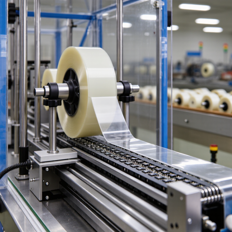
Define Cover Tape Requirements Under EIA-481 Packaging Standards
How to Choose the Right Heat Sealing Cover Tape?
Under EIA-481 packaging standards, cover tape selection begins with the component and carrier tape, not the sealing machine. Confirm the carrier width, pocket pitch, pocket depth, and component height. The cover tape should overlap the carrier’s sealing area evenly. EIA-481-D commonly specifies peel strength between 0.1 and 1.3 N, measured at approximately 300 mm per minute. This range supports secure transport and controlled component removal.
Check the tape’s sealing temperature and dwell time against the carrier material. Polycarbonate, polystyrene, and embossed materials may require different heat windows. Excessive heat can deform pockets or affect moisture-sensitive devices. The IPC/JEDEC J-STD-033 standard also identifies moisture handling as a critical packaging control. For sensitive components, the cover tape must not compromise the dry-pack system or humidity indicator process.
In production trials, inspect peel force across the full reel, not only the first few meters. Uneven coating, dust, or poor roller pressure can create intermittent sealing. A 2024 electronics manufacturing survey reported that process variation remains a major source of packaging defects, especially during high-mix production. The exact percentage differs by survey method. That limitation matters. A tape that performs well in a laboratory may behave differently after storage, transport, or machine-speed changes. Record peel force, visual seal quality, and component retention before approval.
How to Choose the Right Heat Sealing Cover Tape? - Define Cover Tape Requirements Under EIA-481 Packaging Standards
| Requirement Dimension | Recommended Data or Range | EIA-481 Packaging Consideration | Selection Guidance | Verification Method |
|---|---|---|---|---|
| Carrier Tape Compatibility | Select cover tape specifically matched to the carrier tape material, pocket geometry, and sealing layer. Common carrier materials include embossed polymer tape and paper-based tape. | The cover tape must seal continuously over the carrier-tape sealing area without interfering with sprocket holes or component pockets. | Confirm the carrier-tape material, sealing surface, tape width, pocket pitch, and recommended sealing temperature before qualification. | Review the carrier-tape drawing and perform a production-speed sealing trial using the intended equipment. |
| Nominal Cover Tape Width | Common nominal widths include 5.4, 9.3, 13.3, 17.3, 21.3, 25.5, 37.5, 48.4, and 56.5 mm. | The selected width must provide adequate sealing land on both sides of the carrier-tape cavity while maintaining clearance from sprocket holes. | Choose the width specified for the selected carrier-tape format rather than selecting solely from the component size. | Measure tape width and inspect the sealed web for uniform edge coverage across the full reel. |
| Tape Construction | Typical construction consists of a polyester or polyolefin support film with a heat-seal or pressure-sensitive sealing layer. | The sealing layer must be compatible with the carrier-tape surface and must not leave excessive residue after peeling. | Use heat-activated tape for controlled thermal sealing; consider pressure-sensitive tape where the carrier and process are qualified for that system. | Check the supplier technical data sheet, cross-section, seal initiation temperature, and residue after peel. |
| Sealing Temperature | A practical qualification window is commonly established around 120–180 °C, depending on the sealing layer, carrier material, line speed, and dwell time. | EIA-481 defines packaging performance requirements, but the optimum process temperature is dependent on the tape and carrier combination. | Start with the tape supplier's recommended range and qualify the lowest temperature that produces a continuous, secure seal. | Record heater temperature, actual seal-bar temperature, dwell time, pressure, line speed, and peel results. |
| Peel Strength | Use the applicable EIA-481 revision and customer specification for the acceptance limit. A commonly used qualification target for many component-packaging systems is approximately 0.2–1.0 N peel force. | The cover tape must retain components during handling and transport but still peel in a controlled manner during automatic component placement. | Avoid both weak seals, which may open during shipment, and excessive seals, which can cause component ejection, tape tearing, or feeder stoppage. | Perform a controlled peel test at the specified angle and speed. Report average force, peak force, failure mode, and test direction. |
| Peel Behavior | The preferred result is a smooth, continuous peel with no sudden release, tearing, stringing, or adhesive transfer. | Stable peel behavior supports reliable automatic feeding and helps prevent component movement or loss from the pocket. | Select a tape with consistent peel force across the beginning, middle, and end of the reel. | Inspect peel force at multiple reel locations and observe the tape during operation at the maximum intended feed rate. |
| Anti-Static Performance | For electrostatic-sensitive devices, specify a static-dissipative or antistatic cover tape with surface resistance and charge-generation limits defined by the packaging requirement. | The cover tape should not create a damaging electrostatic discharge when peeled, handled, or processed through an automatic feeder. | Use an ESD-control packaging system when the component handling specification requires it; do not rely on color or appearance as proof of ESD performance. | Measure surface resistance and charge generation using the applicable ESD test method under controlled temperature and humidity. |
| Transparency and Inspection | Transparent or translucent film is preferred when visual inspection of component presence, orientation, and pocket fill is required. Opaque film may be used for light-sensitive or confidential components. | The cover tape must allow reliable inspection without causing optical distortion that hides missing, tilted, or damaged parts. | Choose transparency based on the component body, marking contrast, inspection camera, and lighting conditions. | Verify inspection accuracy using filled, empty, misaligned, and damaged-pocket samples. |
| Film Thickness and Flexibility | Typical cover-tape film thickness is approximately 30–100 μm, depending on construction and required stiffness. | The tape must conform to the sealing surface while remaining strong enough to resist tearing and wrinkling during winding and feeding. | Use thinner film for flexibility and optical access; use a more robust construction when puncture resistance or high-speed handling is critical. | Measure thickness, inspect for wrinkles, and run a full-reel winding and feeding trial. |
| Seal Uniformity | The seal should be continuous across both sealing edges, without channels, skips, bubbles, folds, or localized delamination. | Consistent sealing is essential for component retention during reel winding, transportation, and automated feeding. | Control sealing-bar flatness, pressure, temperature distribution, carrier-tape tension, and web alignment. | Perform visual inspection, peel testing, and periodic cross-web checks at the left, center, and right sealing areas. |
| Moisture and Humidity Exposure | Qualify the tape at the intended storage and operating conditions. A common laboratory conditioning point is approximately 23 °C and 50% relative humidity, unless another condition is specified. | Temperature and humidity can change adhesive behavior, peel force, film stiffness, and seal integrity. | Include both normal and worst-case environmental conditions in validation, especially for long storage or overseas transportation. | Condition samples before testing and compare seal strength, peel behavior, and appearance before and after environmental exposure. |
| Storage Life | Store unused reels in the supplier's recommended sealed packaging and within the stated temperature and humidity limits. A typical controlled storage range is approximately 15–30 °C. | Long-term exposure to heat, moisture, dust, and direct sunlight can affect the sealing layer and peel performance. | Use first-in, first-out inventory control and define a retest period for material approaching its recommended shelf life. | Retest aged material for seal strength, peel consistency, visual condition, and feeder performance before release. |
| Reel and Splice Quality | Reels should be wound evenly, free from telescoping and crushed edges, and clearly identified with lot, width, length, and manufacturing information. | Poor winding or uncontrolled splices can cause interruptions, feeder jams, or loss of positional accuracy. | Define maximum splice frequency, splice construction, splice visibility, and splice strength in the purchasing specification. | Inspect reel edges and run the complete reel, including splice areas, through the production feeder. |
| Residue and Cleanliness | The peeled cover tape should leave no visible adhesive residue, particles, fibers, or coating transfer on the carrier tape or component. | Residue can contaminate components, affect soldering or assembly, and interfere with pocket inspection and feeding. | Select a low-residue formulation and qualify it with the actual component finish and carrier-tape material. | Inspect peeled surfaces under suitable lighting and, where necessary, use microscopic or chemical contamination analysis. |
| Process Documentation | The approved specification should identify cover-tape width, construction, sealing temperature, pressure, dwell time, peel criteria, storage conditions, and lot traceability. | EIA-481 compliance depends on the complete carrier-tape and cover-tape packaging system, not on the cover tape alone. | Freeze the validated process window and document any change to material construction, coating, supplier, or manufacturing site. | Maintain incoming inspection records, process capability data, peel-test results, and change-control documentation. |
| Final Qualification Decision | Accept when retention, peel, ESD, cleanliness, inspection, and feeder performance meet the approved specification. Reject when any critical requirement fails or performance is unstable across the reel. | Qualification should represent the complete packaging process and the actual production environment. | Approve the tape only after testing with production equipment, representative components, intended carrier tape, and expected environmental conditions. | Issue a documented qualification report with sample size, test conditions, measured results, deviations, and approval status. |