
425 Sovereign Ct. St. Louis, MO 63011
SEARCH OUR WEBSITE

2026 Top Dicing Machine Types for Global Buyers

Choosing the right Dicing Machine can determine wafer yield, edge quality, and production stability. Global buyers now compare more than cutting speed. They examine kerf width, spindle vibration, cooling control, automation, and after-sales support. A machine that performs well in a laboratory may struggle beside a high-volume production line.

Dr. John H. Lau, a respected semiconductor packaging researcher, has stated, “Yield is the true measure of manufacturing performance.” This principle remains practical for dicing equipment selection. Blade dicing suits many silicon wafers, ceramics, glass, and packaged substrates. Laser dicing can reduce mechanical stress and support narrow kerfs. Stealth dicing offers internal modification before wafer separation. Plasma dicing may serve advanced, fragile structures, although process integration can be demanding. Hybrid systems are also gaining attention.

Performance is not everything. It rarely is. Buyers should inspect sample-cut results, wafer thickness, material hardness, expected throughput, and maintenance access. A clean factory floor, visible coolant filtration, and stable chip pickup can reveal more than a glossy brochure. Regional service teams matter when a spindle alarm stops production at midnight. Energy use and consumable costs also deserve careful calculation.

This guide reviews the 2026 Top Dicing Machine Types for Global Buyers. It compares operating principles, suitable materials, strengths, limitations, and typical purchasing concerns. The categories are useful, but not perfect. Real factories differ. A lower-cost blade machine may outperform a laser system when materials, volumes, and operators are considered together.
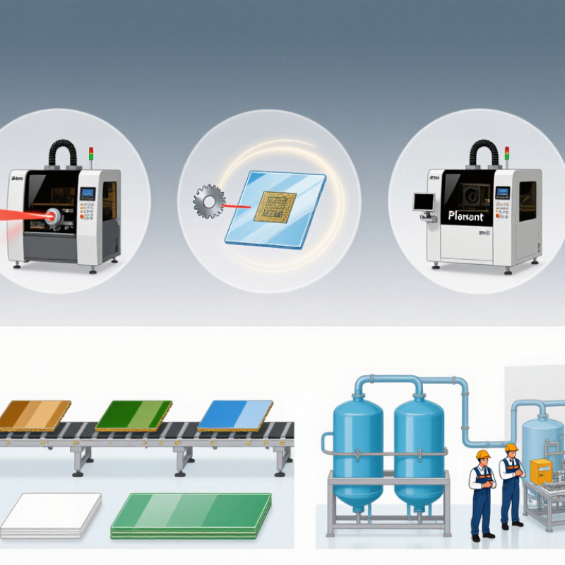
2026 Top Dicing Machine Types for Global Buyers

Dicing Machine Basics and Core Cutting Principles

2026 Top Dicing Machine Types for Global Buyers

Dicing machines separate wafers, substrates, and packaged devices into precise units. Their core task is controlled fracture, not simple sawing. A spindle drives a diamond blade, while coolant limits heat and removes debris. The blade path must balance feed speed, rotation, kerf width, and cutting depth.

Different materials demand different methods. Silicon usually suits high-speed blade dicing. Glass, ceramics, and brittle compound materials may require slower feeds or laser assistance. Blade exposure also matters. Excessive exposure can increase vibration and edge chipping. Insufficient exposure can cause incomplete cuts. Small errors become costly when die spacing is narrow.

SEMI’s 2024 silicon wafer shipment data reported more than 12 billion square inches shipped globally. That volume highlights the need for stable throughput and repeatable alignment. Yole Group’s advanced packaging research also identifies thinner packages and heterogeneous integration as major growth drivers. These trends increase pressure on cut quality, cleanliness, and substrate handling.

In production, buyers should measure chipping, kerf loss, cut depth accuracy, and wafer breakage. Do not judge a machine by speed alone. A faster spindle can create more heat or vibration. That assumption needs testing.

In my view, many selection errors come from using standard recipes on unfamiliar materials. Real samples, cross-section checks, and repeated trials remain essential. Even a well-designed process may need adjustment.


Main Types of Dicing Machines for Different Materials

2026 Top Dicing Machine Types for Global Buyers

Main Types of Dicing Machines for Different Materials

Choosing a dicing machine starts with the material, not the advertised speed. Silicon wafers usually require precision blade dicing or laser dicing. Blade systems offer controlled kerf width and stable production costs. They work well for standard semiconductor wafers and packaged devices. However, coolant selection matters. Poor filtration can leave particles on delicate surfaces. Laser dicing reduces mechanical stress and supports narrow cutting paths. It may suit thin wafers, brittle substrates, and intricate patterns. Heat remains a concern.

Glass and ceramic materials need different control. A diamond blade can cut glass effectively when spindle speed, feed rate, and water flow are balanced. Excessive pressure may create edge chipping or hidden cracks. Ceramics often demand rigid fixturing and gradual feed rates. Small setup errors become visible under magnification. That lesson is easy to underestimate.

Sapphire and other hard crystals typically benefit from specialized diamond blades or laser processes. Blade cutting is familiar and dependable, but tool wear can increase operating costs. Laser methods may improve geometry, although the heat-affected zone requires inspection. Solar cells and thin electronic substrates need gentle handling, accurate alignment, and low vibration. Wire-based cutting can support certain fragile or thick materials, but it may not match the productivity of blade systems. A perfect choice rarely exists. Buyers should test actual samples, measure chipping and kerf loss, and compare maintenance requirements before committing. Small trials often reveal more than a polished specification sheet.

Key Features and Technical Specifications to Compare

For global buyers, dicing machine selection starts with the material, not the brochure. Blade dicing suits silicon, ceramics, glass, and many brittle substrates. Laser dicing reduces mechanical stress and supports narrow kerfs. According to SEMI’s World Fab Forecast, global semiconductor manufacturing capacity was projected to grow about 7% in 2025. That growth increases demand for stable throughput, clean cuts, and repeatable automation.

Compare spindle speed, cutting depth, kerf width, table travel, and positioning accuracy. A practical wafer saw may offer 20,000–60,000 rpm, while advanced systems can exceed that range. Check whether accuracy is specified at room temperature or during continuous operation.

Cooling flow, filtration, vibration control, and particle management also matter. A high speed looks impressive. It may still produce poor edges. Review chipping data, tool life, and yield results from similar materials.

SEMI and industry equipment reports often emphasize automation and yield, but real factory conditions can change the outcome.

Tips:

Request test cuts using your actual material and thickness. Measure edge chipping under magnification. Confirm substrate size, software compatibility, maintenance intervals, and operator training. Ask for noise, power, water, and compressed-air requirements. One overlooked detail is waste handling. It can delay installation. I would also question unusually perfect cycle-time claims; loading, alignment, cleaning, and tool changes are often excluded. A careful comparison should include total cost per usable piece, not only the purchase price.

How to Select the Right Dicing Machine for Global Applications

How to Select the Right Dicing Machine for Global Applications

Global buyers should select a dicing machine by material, thickness, kerf width, and required yield. Silicon wafers, glass substrates, ceramics, and compound semiconductors react differently during separation. Blade systems remain practical for many standard wafers. Laser and stealth dicing can reduce mechanical stress on fragile materials. However, laser solutions may require higher capital investment and tighter process control.

SEMI’s World Fab Forecast, published in 2024, reported continued expansion in global semiconductor manufacturing capacity. That expansion increases demand for stable, repeatable back-end equipment. Fortune Business Insights also projects long-term growth in the semiconductor manufacturing equipment market through 2032. These figures support investment, but they do not identify the best machine for every factory. A high-speed model can underperform when dust extraction, spindle accuracy, or operator training is weak.

Ask suppliers for application trials using your actual substrate and street layout. Measure chipping, die strength, throughput, water consumption, and maintenance intervals. Check regional voltage requirements, safety documentation, spare-parts availability, and service response times. Automation may improve consistency, yet complex software can create problems for smaller teams. That matters.

A reliable selection process should compare total ownership cost, not only purchase price. Review five-year consumables, blade usage, calibration needs, and rejected-die costs. I would also request production data from comparable materials. Marketing claims are useful, but real samples reveal more.

2026 Top Dicing Machine Types for Global Buyers – How to Select the Right Dicing Machine for Global Applications
Dicing Machine Type Primary Cutting Method Suitable Materials Typical Workpiece Size Typical Kerf or Cut Width Typical Throughput Profile Main Advantages Key Limitations
Manual Dicing Saw Operator-guided, water-cooled diamond blade Silicon wafers, glass, ceramics, quartz, sapphire, compound semiconductor substrates and small packaged parts Small samples to approximately 150–200 mm substrates, depending on the worktable and chuck Approximately 30–300 µm, depending on blade thickness, material and cutting conditions Low; appropriate for laboratory work, prototypes and occasional production Low initial investment, simple operation, flexible fixture options and convenient process development Dependent on operator skill; lower repeatability, limited automation and higher variation in alignment and yield
Semi-Automatic Blade Dicer Programmable X-Y positioning with operator-assisted loading and unloading Silicon, glass, ceramics, LTCC, LEDs, sensors, electronic packages and other brittle substrates Commonly 100–200 mm wafers or panels; some configurations support larger workpieces Approximately 20–200 µm with suitable precision blades Low to medium; suitable for pilot lines and flexible batch production Better alignment and repeatability than manual systems, moderate cost and adaptable to varied products Requires operator intervention; wafer handling, inspection and process monitoring may remain partly manual
Fully Automatic Blade Dicer Computer-controlled diamond blade with automatic alignment, cutting and workpiece handling Silicon wafers, compound semiconductors, ceramic substrates, glass, MEMS structures and advanced packages Typically 150–300 mm wafers; platform capacity varies by machine configuration Approximately 15–150 µm, subject to blade specification and material properties Medium to high; designed for repeatable production batches and integrated manufacturing lines High positional accuracy, recipe control, reduced labor input, automated inspection options and consistent process conditions Higher purchase and maintenance cost; requires qualified setup, utilities, fixturing and process engineering
Ultra-Thin Blade Dicer High-speed spindle using a thin diamond blade and precision coolant delivery Silicon, glass, ceramic, sapphire and other materials where material loss must be minimized Usually 100–300 mm wafers or precision substrates Approximately 10–80 µm, depending on blade construction and process stability Medium to high for narrow streets and high part counts Low material waste, narrow streets, efficient use of wafer area and suitability for small dies More sensitive to blade wear, vibration, spindle condition, coolant quality and workpiece thickness variation
Laser Dicing Machine Focused pulsed or continuous laser beam for ablation, thermal separation or groove formation Silicon, glass, ceramics, sapphire, polymers, thin films and selected compound semiconductor materials Commonly 100–300 mm wafers and precision panels, depending on optical travel and workholding Approximately 5–50 µm for the laser interaction zone; the effective separation width depends on the process Medium to high; strongly dependent on material absorption, thickness, laser power and cut strategy No mechanical blade contact, narrow cuts, low cutting force and capability for some delicate or multilayer structures Potential heat-affected zone, debris or redeposition; higher optical-system cost and material-specific process development
Stealth Dicing System Laser-induced internal modification followed by expansion or controlled breaking Selected transparent or semi-transparent materials, including silicon, glass and some crystalline substrates Often 150–300 mm wafers or panels, subject to material transparency and equipment design Very narrow surface opening; the internal modified layer is typically designed to remain within the intended street Medium to high after recipe optimization; suitable for high die counts and low-chipping requirements Low surface chipping, minimal kerf loss and reduced mechanical contact during the separation stage Material and wavelength dependent; unsuitable for many opaque or highly absorbing materials and requires precise separation control
Plasma Dicing System Dry plasma etching along patterned streets, normally after suitable masking and process preparation Primarily semiconductor wafers and selected thin-film or microfabricated structures compatible with plasma chemistry Commonly 200–300 mm wafers in semiconductor manufacturing environments Typically defined by the street layout and etch profile; can achieve very narrow separation lanes with optimized processes High in dedicated, stable production flows; less suitable for frequent product changes Low mechanical stress, no blade wear, good compatibility with fragile structures and potential for narrow streets Requires vacuum equipment, masks, gas systems and process expertise; higher facility and qualification requirements
Ultrasonic or Assisted Dicing System Diamond blade cutting enhanced by ultrasonic vibration or another controlled assistance method Hard, brittle and difficult-to-machine materials such as ceramics, glass, sapphire and selected crystals Small parts to wafer-scale substrates, depending on the fixture and travel range Approximately 30–200 µm, depending on blade and workpiece properties Low to medium; commonly selected for challenging materials rather than maximum volume Can reduce cutting force, improve edge quality and support materials that are difficult to process with conventional sawing Additional system complexity, specialized tooling and possible limitations in cycle time and maintenance
Selection guidance: Choose a blade dicer when flexibility and broad material compatibility are priorities; choose laser or stealth dicing when low mechanical force and narrow streets are important; consider plasma dicing for qualified high-volume semiconductor flows; and select manual or semi-automatic equipment for prototypes, laboratories and frequent product changes. Actual performance depends on substrate thickness, street width, die size, blade or laser parameters, coolant, alignment accuracy, fixturing, cleanliness requirements and factory automation.

Safety, Maintenance, and Operating Considerations

2026 Top Dicing Machine Types for Global Buyers

Safety, maintenance, and operating discipline often matter more than cutting speed. Different dicing machines suit vegetables, fruit, meat, or prepared foods. However, every model needs a guarded cutting chamber, stable feet, and accessible emergency stops. Operators should verify that covers and interlocks work before production begins. Loose clothing must stay away from rotating parts. Cut-resistant gloves may help during cleaning, but never near moving blades.

Daily checks should include blade condition, fasteners, drainage, and unusual vibration. A dull blade can crush products, increase waste, and overload the motor. Clean food-contact areas after each shift, following the machine’s approved sanitation procedure. Keep electrical controls dry. Apply lubricants only where specified. Maintenance records should note dates, parts, faults, and corrective actions. Small omissions happen, even in experienced teams. A second inspection can catch them.

Tips: Train operators with real product samples, not only manuals. Feed products steadily, without forcing them into the inlet. Stop the machine before removing jams. Use lockout procedures during blade changes or internal cleaning. Measure cut size regularly with a simple gauge, because visual checks can be misleading. Listen for new sounds. A quiet machine is not always a healthy one. Review near-misses without blame, and adjust work instructions when repeated mistakes appear.

Scroll to Top